 Easy Laser Systems "Easy to learn and Easy to use"
• SHAFT ALIGNMENT
• SHEAVE/PULLEY ALIGNMENT
• VIBRATION MEASUREMENT
• TWIST MEASUREMENT OF BASES
• STRAIGHTNESS MEASUREMENT
GENERATION XT – THE AGE OF MEASUREMENT INDEPENDENCE IS HERE!
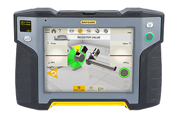
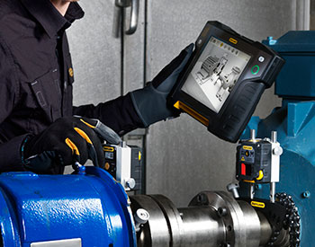
The Easy-Laser® XT770 is the most powerful of our Generation XT alignment systems. It allows you to display alignment data on different handheld devices, including our own Easy-Laser® XT11 ergonomic and rugged, IP66/67-approved shock proof alignment computer, which includes a built-in 13MP camera for documentation and HDMI video output.
With Easy-Laser XT770 you can perform laser shaft alignment of horizontal and vertically/flange mounted machines, but also align unlimited machine trains, measure twist of foundation, soft foot, bearing clearance, and more. The EasyTrend program allows you to keep track of machine movement over time. That is useful when checking for thermal expansion and pipe strain issues among other things.
2-axis PSDs (position sensitive detectors) permit adjustment of your machine both vertically and horizontally at the same time, with measuring units in any position. We call it 360° Live adjustment. Easy-Laser XT measuring units and display unit are shockproof and rated both IP66 and IP67 water and dustproof.

View The Complete Product Line:
EASY-LASER® SYSTEMS - GENERATION XT
EASY-LASER® SYSTEMS - E-SERIES
ACCESSORIES
Parallelism Alignment
Check Parallelism Between Rolls
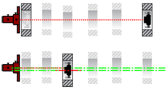
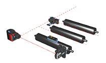 The parallelism equipment is used to align the rolls. The most common method is as follows: The D22 laser transmitter (on tripod) is aligned in parallel with the machine. The D46 Angular prism (also on a tripod) then deflects the laser beam parallel with the rolls instead. A D5 detector unit is positioned horizontally at one end of the roll and the measurement value is recorded. The detector unit is then moved to the other end of the roll and the measurement value recorded.
This procedure is followed for the rest of the rolls that are to be measured. The display unit shows the rolls’ positions, both graphically and digitally, in relation to any roll or the base line.
Checking The Level Of The Rolls
To check the level of the rolls, the D22 laser is levelled according to the built-in vials. Detector D5 is then placed vertically at the ends of the rolls, and the measurement values are recorded at each position. Because the “laser beam” is levelled, the measurement result gives the position of the roll in relation to this.
Flatness Measurement Of Wire End
The D22 laser and the D5 detector unit are used for flatness measurement of the wire end. The detector is placed at the marked points on the surface, the laser beam is aimed at the detector and the values are recorded. The result shows the flatness of the surface in relation to three zero (reference) points that can be changed if desired.
Other Examples Of Alignment Requirements
Other examples of alignment requirements are alignment between gearbox and cardan-coupled shafts, shaft alignment between pumps and motors, sheave/pulley alignment for fans, straightness measurement of rolls, parallelism and flatness of foundations, etc.
Turbine Alignment
Measuring The Straightness Of Diaphragms And Bearing Journals
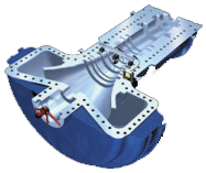 When measuring the straightness of diaphragms and bearing journals in a steam or gas turbine, the Turbine equipment (system E960) is used. The laser transmitter is mounted at one end of the turbine’s centre line (usually a bearing journal). The detector fixture is placed at each part of the diaphragm that has to be measured. The measurement values are recorded at three positions (9, 6 and 3 o’clock) by rotating the detector probe.
 The measurement result displays the straightness of the bearing and the diaphragm’s centre line, both vertically and horizontally, compared with two zero (reference) points. The flatness of the parting surface is measured with laser D22 and detector E7. The measurement values are recorded at the marked points on the surface, after which three zero points are selected to which the flatness refers.